Table of Contents >> Show >> Hide
- What “Capacitive Touch” Really Means (No Lab Coat Required)
- The Three Best Ways to Hide Touch Buttons in a 3D Print
- Design Rules That Make Hidden Touch Buttons Actually Work
- Pick Your Touch Brain: Controller Options That Play Nice With 3D Prints
- Step-by-Step: The “Pause Print, Insert Copper Tape, Resume” Method
- What you’ll need
- 1) Design the “button window” into the print
- 2) Choose a sensible wall thickness
- 3) Slice and insert a pause at the right layer
- 4) Insert the tape (and don’t wrinkle it like a sad burrito)
- 5) Resume the print and seal the electrode
- 6) Wire it to your controller
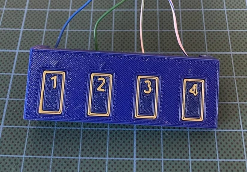
- Example: MPR121-style wiring concept
- Tuning and Calibration: Turning “It Sorta Works” Into “It Ships”
- Project Ideas That Feel Like Magic (But Are Just Physics)
- Troubleshooting: When Your Print Thinks It’s Possessed
- Real-World Maker Experiences (The Stuff You Only Learn After the Third Reprint)
- Conclusion
- SEO Tags
Mechanical buttons are greatright up until your project lives in a kitchen, a workshop, a bathroom, a robot, or anywhere
that treats tiny moving parts like a snack. If you want a clean, waterproof-ish interface with zero clicky hardware showing,
capacitive touch is the “now you see it, now you don’t” trick for makers: the button is there, but the plastic never has to move.
In this guide, you’ll learn how to hide capacitive touch buttons inside a 3D-printed part (without turning your enclosure into
a haunted object that triggers itself at 2 a.m.). We’ll cover proven build methods, real design rules (thickness matters),
controller options (from one-button ICs to multi-channel boards), and tuning tips that save you from the “why does it only work
when I’m holding a coffee?” phase.
What “Capacitive Touch” Really Means (No Lab Coat Required)
A capacitive touch sensor is basically measuring a tiny electrical effect called capacitance. Your body acts like a big squishy
conductor connected to the world. When your finger gets close to (or touches) a conductive “electrode” (copper tape, conductive
fabric, a PCB pad, etc.), the capacitance changes. A touch controller notices that change and says, “Ahahuman detected!”
The magic part: that electrode can sit behind a non-conductive “overlay” like PLA, PETG, acrylic, or wood veneer.
The overlay becomes your button face. No holes. No moving parts. No crumbs inside your electronics.
The Three Best Ways to Hide Touch Buttons in a 3D Print
1) Copper tape embedded behind a thin wall (the crowd favorite)
This is the go-to method because it’s cheap, reliable, and easy to prototype. You print most of the part, pause at a layer,
stick copper tape inside a recess, then resume printing so the printer “seals” it in. The user touches the outside surface;
the electrode is trapped safely underneath like a fossil from the Age of Over-Engineering.
- Pros: Fast, repeatable, great sensitivity, easy to repair (reprint + re-tape).
- Cons: Requires a pause-and-insert step; adhesives can lift if your recess is sloppy.
2) Conductive filament electrodes (cool, but know its limits)
Conductive PLA/TPU can print an electrode directly into your partno tape required. The catch is that most “conductive”
filaments are resistive compared to copper, so they’re better for touch pads than for power or signal traces.
Still, for hidden touch areas (especially big pads), it can be slick.
- Pros: Fully printed electrode geometry; no manual insert.
- Cons: Higher resistance; printing and wiring can be fiddly; not ideal for carrying current.
3) A PCB, flex circuit, or conductive paint behind the panel (the “product-grade” route)
If you want consistent performance across many builds, a PCB with proper pad shapes, ground pours, and spacing is hard to beat.
You can mount it behind the printed face, use standoffs, and keep all touch electrodes identical. Conductive paint works too,
especially for artistic surfaces, but it’s less standardized.
Design Rules That Make Hidden Touch Buttons Actually Work
Overlay thickness: your #1 success factor
Capacitive sensing can work through plastic, but sensitivity drops as the overlay gets thicker. For many DIY builds,
keeping the electrode just under the surfaceoften around sub-millimeter to a couple millimetersmakes life easier.
A common maker trick is placing copper tape a few layers under the surface (for example, around 0.6 mm when printing 0.2 mm layers).
Practical tip: if you need a thicker, sturdier face, compensate by using a larger electrode and a touch controller that supports
tuning thresholds and auto-calibration.
Electrode size and shape: bigger is easier (to a point)
For simple buttons, round or square electrodes in the ballpark of “fingertip-ish” sizes are easiest to tune. Many design guides
suggest button dimensions on the order of several millimeters up to around a centimeter-plus depending on overlay thickness.
If your overlay is thicker, you usually want a larger pad.
- Round/square pads are easiest for single buttons.
- Sliders/wheels work great, but require more careful geometry and firmware filtering.
- Ring electrodes can reduce sensitivity at the center and help with “touch around the edge” UX.
Grounding and shielding: preventing “ghost touches”
Capacitive sensors are sensitivesometimes too sensitive. Long wires, noisy power supplies, and nearby mains wiring can all
inject interference. The fix is boring and effective: good grounding, short electrode leads, and thoughtful routing.
- Keep the wire from electrode to controller short.
- Route electrode wires away from high-current traces, motors, and DC-DC converters.
- Consider a ground reference plane (or a grounded shield) where appropriatesome controllers and design guides show
guard rings / ground pours that improve stability. - Remember: even your wire can become touch-sensitive, so don’t run it right under the area people will touch.
Material quirks: PLA vs PETG vs “mystery filament from 2019”
Most common plastics (PLA, PETG, ABS) are fine overlays. The bigger variables are thickness consistency, air gaps,
humidity, and how your print is assembled. Air gaps can change the effective dielectric behavior; finger moisture can increase
coupling; wood veneer can behave differently depending on absorbed moisture. If your build must work in a humid room, test there.
Pick Your Touch Brain: Controller Options That Play Nice With 3D Prints
Option A: A dedicated touch controller IC (recommended for multi-button panels)
Boards based on capacitive touch controller chips are popular because they’re designed for the job: stable sensing,
adjustable thresholds, and multiple channels. The MPR121 is a classic for multi-input DIY builds and supports multiple electrodes
plus proximity-style tricks if you want a larger sensing area.
Option B: Single-button touch ICs (simple and satisfying)
If you just need one hidden buttonpower, wake, a secret latchsingle-channel touch chips are delightfully straightforward.
Many support external electrodes and are designed to sense through dielectrics like plastic and glass, with typical guidance on
electrode size versus overlay thickness.
Option C: ESP32 touch pads (great when you’re already using an ESP32)
Many ESP32 variants include built-in capacitive touch sensing on certain pins. It’s convenient, but it can be more susceptible
to noise than a dedicated controller, and the tuning experience depends on your firmware stack. Still, for smart-home nodes,
lamps, and quick prototypes, it’s hard to beat “no extra chip.”
Step-by-Step: The “Pause Print, Insert Copper Tape, Resume” Method
What you’ll need
- 3D printer + filament (PLA/PETG are fine)
- Copper foil tape (conductive adhesive is a nice bonus)
- Touch controller (MPR121 board, single-button board, or ESP32 touch pin)
- Hookup wire, soldering basics (or crimp/alligator options)
- Design with a shallow recess or pocket for the tape
1) Design the “button window” into the print
Create a thin wall where the user will touchthink of it as the button face. Behind it, add a flat pocket sized for your tape pad.
If you want a labeled interface, emboss or deboss icons on the outer surface. (Your users will thank you. Your future self will too.)
2) Choose a sensible wall thickness
For a first build, aim for a thin, consistent overlay. Many makers start with something like a few top layers over the electrode
and then adjust based on performance. If you go thick, plan for bigger electrodes and more tuning.
3) Slice and insert a pause at the right layer
In your slicer, add a pause just before the printer starts closing the pocket. The goal: the pocket is open so you can place the tape,
but you still have enough layers left to seal it in.
4) Insert the tape (and don’t wrinkle it like a sad burrito)
- Cut a pad of copper tape (start with roughly 10–20 mm wide for a button; adjust later).
- Stick it flat into the pocket. Smooth it down.
- Attach a wire: solder to the tape (if your tape and technique allow), or fold a small tab for a screw/clip contact.
- Route the wire out through a channel so it won’t get crushed by the nozzle.
5) Resume the print and seal the electrode
Let the printer close the pocket. Now your electrode is safely embedded. Congratulations: you’ve created a button that is
simultaneously invisible and extremely smug.
6) Wire it to your controller
With a multi-channel controller, each electrode pad goes to one input. With a single-button IC, it goes to the electrode pin.
With an ESP32, connect the pad to a touch-capable GPIO.
Example: MPR121-style wiring concept
Tuning and Calibration: Turning “It Sorta Works” Into “It Ships”
Set thresholds like you’re training a picky pet
Most controllers let you set a touch threshold and a release threshold. If you set them too low, you’ll get false touches.
Too high, and your users will have to press like they’re trying to start a fire.
- Start conservative: avoid false triggers first, then increase sensitivity.
- Use hysteresis: release threshold lower than touch threshold helps prevent chatter.
- Debounce in software: require a stable touch for, say, 30–80 ms before you act.
Watch out for “the wire is the sensor”
Long leads can act like antennas and can become touch-sensitive themselves. Keep runs short, route them away from the touch face,
and consider shielding or twisting with ground if you have noise trouble.
Environmental drift is real
Humidity, temperature, and a person’s footwear (yes, really) can affect capacitive readings. Many touch systems use baseline tracking
(auto-calibration) so the sensor slowly adapts. The trick is tuning it so it adapts to environment changes but not to an actual finger.
Project Ideas That Feel Like Magic (But Are Just Physics)
A “waterproof” bathroom fan timer
Put hidden touch buttons behind a smooth printed faceplate. Add LED feedback behind thin light pipes. No mechanical switches to corrode,
and it wipes clean.
A lamp with stealth dimmer zones
Use three embedded pads: power, dim down, dim up. Bonus points if your lamp “snoozes” when you tap twice.
A secret drawer latch
Touch a specific spot on the print (or a sequence, if you’re feeling dramatic), trigger a servo, and pop a hidden compartment.
It’s the adult version of a spy movie, minus the budget.
Troubleshooting: When Your Print Thinks It’s Possessed
Problem: false touches when a motor starts
- Add decoupling and clean power (noise is the enemy).
- Move touch wires away from motor wiring and DC-DC converters.
- Use a dedicated touch controller and proper grounding.
Problem: only works when you touch with a wet finger
- Overlay may be too thick; thin the wall or increase electrode size.
- Increase sensitivity (lower threshold) carefully, then add debounce.
- Improve ground referencefloating systems can be less consistent.
Problem: touch works… until you mount the PCB in the enclosure
- Your mechanical stack-up changed (air gaps, grounding, nearby metal).
- Re-run baseline calibration after final assembly.
- Check for unintended coupling to screws, standoffs, or shielding tape.
Real-World Maker Experiences (The Stuff You Only Learn After the Third Reprint)
Makers who build hidden capacitive buttons in 3D prints tend to report the same arc: it works instantly in a quick bench test,
then gets weird the moment you assemble it “for real.” That’s not failureit’s just the interface between physics and whatever
chaotic geometry your enclosure created.
One common experience: the first electrode is too small. On paper, a tiny copper square feels elegant. In practice, the overlay is
thicker than you think (extra top layers, a slight air gap, a textured surface), and your fingertip isn’t a perfect lab probe.
The fix is usually hilariously simple: make the pad bigger. Makers often end up with pads closer to “large postage stamp” than
“confetti square,” especially when hiding the sensor under a sturdier panel.
Another repeat offender is the “mystery air gap.” If the copper tape isn’t pressed flat into its pocket, or the print bridges over
a cavity unevenly, you can create a small void. That void changes the effective dielectric stack and can reduce sensitivity or create
inconsistent behavior across the pad. The practical workaround is to design a clean, flat recess and to place the tape carefullythen
seal it with a few consistent layers. Some makers even add a tiny printed “compression rib” so the tape is forced flat when the print
closes up.
Noise shows up as soon as you add real electronics: motors, LED drivers, switching regulators, long USB cables, or a power brick that
should have been retired years ago. Builders often notice that touches trigger when a relay clicks, or readings drift when an LED strip
changes brightness. The pattern is predictable: capacitive sensing is measuring tiny changes, and noisy systems throw tiny chaos everywhere.
The “maker-grade” solution is rerouting and grounding: shorten electrode wires, keep them away from noisy lines, and make sure the controller
shares a solid ground reference with the rest of the device. When that’s not enough, people move from raw microcontroller touch pins to a
dedicated controller that’s built to handle baseline tracking and filtering.
There’s also a human-factor discovery that surprises first-timers: users expect feedback. A hidden button with no click is like a whisper
in a rock concert. Makers frequently add a subtle LED blink, a short beep, or a tiny vibration motor so the interface feels intentional.
If your project is meant for guests (or future you at 3 a.m.), visible cues mattericons, a slight surface texture difference, or a gentle
backlight. A completely invisible button is fun for exactly five minutes, then it becomes a scavenger hunt.
Finally, many builders learn the “final assembly rule”: calibrate in the final housing. A touch setup that’s perfect on the bench can shift
when you screw the PCB down, add a metal insert, or mount the device near a grounded appliance. The baseline changes because the environment
changed. The best experiences come from treating capacitive touch like a system, not a component: mechanical stack-up, electrode geometry,
wiring, grounding, and firmware thresholds all work together. When they do, the result feels like a polished consumer productexcept you made it.
Conclusion
Hidden capacitive touch buttons are one of the easiest ways to make a 3D-printed project feel “finished.” They’re clean, durable,
and perfect for enclosures that need to stay sealed. Start with the simplest methodembedded copper tape behind a thin, consistent wallthen
level up with better grounding, smarter electrode geometry, and a controller that supports tuning. You’ll spend less time fighting random
triggers and more time enjoying the fact that your “button” has no button.