Table of Contents >> Show >> Hide
- Start Here: What Architect’s Drawings Really Are
- The Anatomy of a Drawing Set (AKA: How the Binder Is Trying to Help You)
- Before You Read Lines, Read Words
- Scale and Dimensions: Measure Twice, Cry Zero Times
- The Big Five Drawing Types (And How to Read Each One)
- Symbols, Tags, and Callouts: The Drawing’s Hyperlinks
- Schedules: The Shopping List Hiding in Plain Sight
- Don’t Forget the “Other” Drawings: Structural and MEP Matter
- A Practical 15-Minute Method to Read a Plan Set (Even If You’re New)
- Common Mistakes (So You Don’t Become a Cautionary Tale)
- How to Ask Better Questions (And Get Faster Answers)
- Conclusion: Read Drawings Like a Detective, Not Like a Tourist
- Real-World Experiences: What It Actually Feels Like to Learn Plan Reading (And Why It Gets Easier)
Architect’s drawings can feel like a secret languageone that everyone on a jobsite speaks fluently except the person holding the plans.
The good news: you don’t need a beret, a drafting table, or a tragic love story in Paris to understand them. You just need a system.
This guide will show you how to read architectural drawings (aka construction plans, plan sets, or the not-quite-accurate-but-everyone-says-it “blueprints”)
with confidence. We’ll cover how drawing sets are organized, what the symbols actually mean, how to follow callouts like hyperlinks,
and how to spot the details that prevent expensive “oops” moments.
Start Here: What Architect’s Drawings Really Are
Architect’s drawings are the graphic instructions for building (or remodeling) a project. They usually live inside a bigger package called
construction documentswhich can include written specifications, schedules, code notes, and other paperwork that makes contractors sigh deeply.
The drawings show intent: what goes where, how big it is, how it connects, and what materials and components are expected.
Your goal when reading a plan set isn’t to admire the linework (though some of it is gorgeous). Your goal is to answer practical questions:
What am I building? Where does it go? How does it connect? What’s the “right” version of this sheet?
The Anatomy of a Drawing Set (AKA: How the Binder Is Trying to Help You)
1) Title Sheet + Drawing Index: The Table of Contents You Should Actually Use
Most sets start with a title sheet that lists the project information and an index of drawings. If you skip this, you’ll spend the next hour
playing “Where’s Waldo?” with wall sections. The index tells you what sheets exist and often how they’re grouped: architectural, structural, mechanical, electrical, plumbing, and so on.
2) The Title Block: The ID Card of Each Sheet
The title block (typically along the bottom or right edge) is where you confirm the basics: sheet title, sheet number, project name, date, and sometimes the drawing scale.
It can also include the architect/engineer info and approval stamps.
If you only learn one habit, learn this: check the title block and revision info before trusting anything else.
If you’re looking at an outdated sheet, you can be 100% correct and still 100% wrong.
3) Sheet Numbers: The Filing System That Makes Chaos Slightly Less Chaotic
Many drawing sets follow a standardized approach where sheet numbers indicate the discipline and the drawing type.
You’ll often see discipline letters like:
A (Architectural), S (Structural), C (Civil), M (Mechanical),
E (Electrical), P (Plumbing), FP/F (Fire Protection), L (Landscape), and G (General).
The number series often hints at the content type. For example:
0 = general info (legends, notes), 1 = plans, 2 = elevations,
3 = sections, 5 = details, 6 = schedules/diagrams.
So a sheet like A-101 is usually an architectural plan sheet, while A-601 is often schedules and diagrams.
Before You Read Lines, Read Words
Legends, Abbreviations, and General Notes: The Rosetta Stone Pages
Plan sets typically include a legend (symbols key), abbreviations, and general notes.
Here’s why they matter: not every firm draws the same way, and not every symbol is universal.
The legend tells you what this set means by a certain icon, hatch pattern, or tag.
Pro move: scan for notes that say things like NTS (Not to Scale), “VERIFY IN FIELD,” “TYPICAL,” or “SEE SPECIFICATIONS.”
Those four phrases are basically the plan set’s way of saying, “Don’t freestyle this.”
Specifications: The “Yes, But…” of Construction Documents
Drawings show the where and the shape. Specs often define the what: product quality, installation requirements, and performance expectations.
If a drawing says “Tile,” the specs might say which tile, what substrate, which grout, and how waterproofing is handled.
Scale and Dimensions: Measure Twice, Cry Zero Times
Architectural Scale vs. Engineering Scale
In U.S. practice, building floor plans are often drawn at architectural scales like
1/4" = 1′-0" or 1/8" = 1′-0".
Site or civil drawings may use engineering scales (like 1" = 20′ or 1" = 50′).
This matters because your eyes will lie to youpolitely, but consistently.
Golden Rule: Trust Dimensions Over the Ruler
Printed sheets can be scaled incorrectly. PDFs can be zoomed. Copiers can distort.
That’s why drawings usually provide written dimensions. If a wall-to-wall dimension says 12′-6", believe that
over what your on-screen measuring tool thinks it seesunless the sheet is clearly marked to be used with digital scaling.
Quick sanity check:
if a bedroom “looks” the size of a basketball court, it probably isn’t. Check the dimensions and the scale, then double-check you’re on the right sheet.
The Big Five Drawing Types (And How to Read Each One)
1) Site Plan: The Bird’s-Eye “Where Is This Thing Going?” View
A site plan shows the building in relation to the property: setbacks, driveways, sidewalks, utilities, grading, landscaping, and orientation.
Look for a north arrow, property lines, easements, and key dimensions to lot lines.
Example: If you’re adding an addition, the site plan might show the new footprint and distances to the property boundary.
That’s the difference between “approved project” and “surprise conversation with a zoning official.”
2) Floor Plans: The Main Event
A floor plan is a horizontal “slice” through the buildingtypically cut around 4 feet above the floorso you can see walls, doors, windows, stairs, and room layouts.
Floor plans often include:
- Room names (Kitchen, Bedroom 2, Mechanical)
- Dimensions (overall and partial)
- Door and window tags (like D3 or W12)
- Wall types (sometimes labeled with codes like W1, W2)
- Grid lines (common on larger projects)
Example: You see a door tag D5 next to a door swing symbol. That tag usually connects to a door schedule that tells you
the door’s size, material, fire rating (if required), and hardware notes. The plan shows location; the schedule shows what you’re actually ordering.
3) Elevations: The “Standing in Front of It” View
Elevations show vertical facesexterior or interior. Exterior elevations might show windows, doors, roof lines, exterior materials, and heights.
Interior elevations often show cabinetry, tile layouts, and fixture placement.
If you’ve ever wondered why two people can look at the same kitchen plan and imagine totally different designs, it’s because the floor plan is only half the story.
Elevations add the “what it looks like” layer.
4) Sections: The Cut-Through That Explains How It’s Built
A section is like taking a giant knife through the building and looking at the cut. Sections reveal floor-to-floor heights, ceiling conditions,
roof assemblies, foundations, and how major parts stack.
Example: A floor plan might show a staircase. A section will show whether that stair clears the ceiling, how thick the floor assembly is, and
where guardrails and landings actually land (no pun intended).
5) Details: The Zoom-In That Prevents Leaks, Cracks, and Regret
Details show specific connections: window flashing, wall intersections, waterproofing at showers, parapet caps, stair handrails, and more.
When people say, “The devil is in the details,” they’re not being poetic. They’re talking about water intrusion.
If a plan set were a movie: plans are the plot, elevations are the cinematography, sections are the behind-the-scenes,
and details are the stunt coordinator shouting, “DO NOT TRY THAT WITHOUT THE RIGHT FASTENERS.”
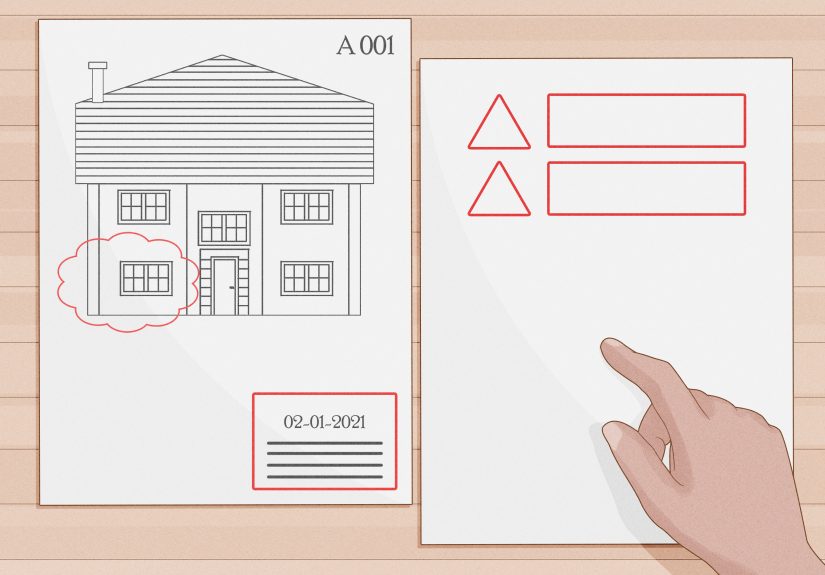
Symbols, Tags, and Callouts: The Drawing’s Hyperlinks
Section Marks and Detail Callouts
Callouts connect one drawing to another. A common format is “detail number / sheet number.”
For example, a bubble might read 5/A-501, meaning “look at detail 5 on sheet A-501.”
Section markers work similarly: they tell you where the cut is taken and where to find the section view.
If you follow callouts consistently, drawings stop feeling like scattered pages and start behaving like an organized system.
Line Weights and Types: Thick, Thin, Dashed, and Not Just for Decoration
Generally, thicker lines indicate elements that are being “cut” (like walls in plan).
Thinner lines often show edges beyond the cut plane.
Dashed lines can show items above or hidden (like upper cabinets, overhead beams, or soffits).
The legend and notes will tell you what conventions this set uses.
Levels, Datums, and “Up/Down” Information
Look for elevation markers and level callouts, like EL. 100′-0" or similar.
These are critical for understanding slopes, steps, ceiling heights, and how floors relate to one anotherespecially on renovations where nothing is perfectly square or level.
Schedules: The Shopping List Hiding in Plain Sight
Schedules are tables that organize repeated elements. If plans are the “map,” schedules are the “inventory.”
Common schedules include:
Door Schedules
Door schedules typically include door size, type, material, rating (if applicable), and remarks.
That little D2 tag on the plan is basically a shortcut to a lot of information.
Window Schedules
Window schedules can include size, operation type (fixed, casement, sliding), glazing notes, and sometimes performance requirements.
If you’re comparing bids, window schedules are a great place to check whether everyone is pricing the same thing.
Finish Schedules
Finish schedules list materials by room: flooring, base, wall finish, ceiling type.
If you’ve ever seen a project go off the rails because “We thought that wall was paint, not tile,” this is where that misunderstanding gets fixed.
Don’t Forget the “Other” Drawings: Structural and MEP Matter
Structural Sheets (S): The “Can It Hold Up?” Pages
Structural drawings cover foundations, framing, beams, columns, connections, and reinforcement.
Architects design the space; structural engineers help make sure gravity doesn’t win.
MEP Sheets (M, E, P): The “It Has to Work” Pages
Mechanical, electrical, and plumbing drawings show ductwork, equipment locations, panels, circuits, outlets, piping, vents, and fixtures.
Even on smaller projects where MEP is simplified, you still want to confirm:
Where does the air go? Where does the water go? Where does the power go?
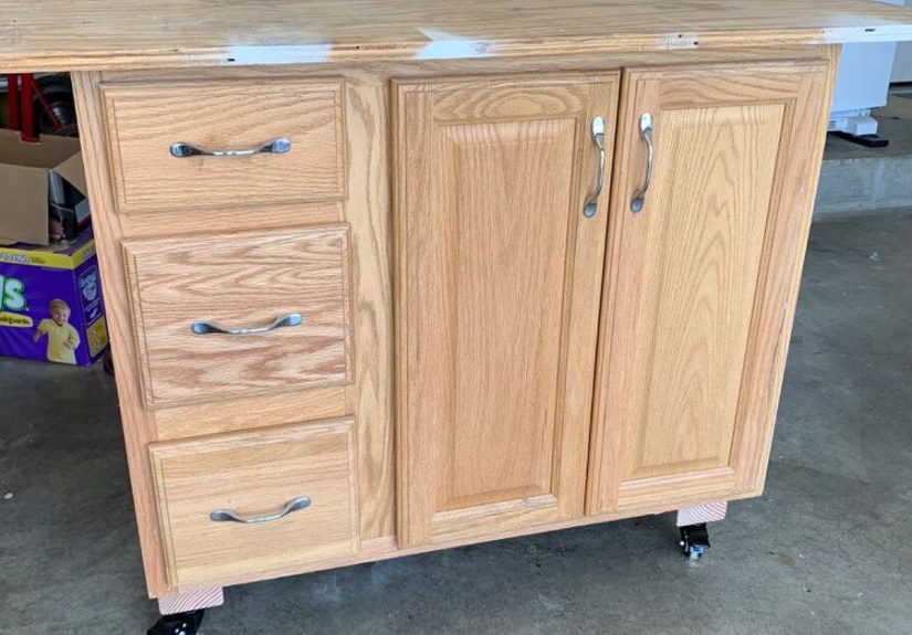
Example: A floor plan might show a clean kitchen island. The electrical plan might show required outlets. The mechanical plan might show a downdraft vent.
The plumbing plan might show a sink and vent path. Reading all of them together prevents the classic surprise:
“Wait, there’s a pipe where my drawer needs to be?”
A Practical 15-Minute Method to Read a Plan Set (Even If You’re New)
- Check the title sheet and drawing index. Know what exists before hunting for it.
- Confirm the sheet is current. Look at dates and revision info.
- Scan general notes, abbreviations, and legends. Decode the set’s language.
- Identify the key plans. Site plan, floor plans, and any demolition plans for remodels.
- Follow callouts. Any time you see a bubble, chase it to the referenced sheet/detail.
- Cross-check schedules. Doors, windows, finishesconfirm what’s specified.
- Flip to sections and details. Especially where water, roofs, and foundations are involved.
- Quick coordination scan. Compare architectural intent with structural and MEP realities.
Common Mistakes (So You Don’t Become a Cautionary Tale)
Mistake 1: Ignoring Demolition vs. New Work
Remodel sets often include demolition plans. These show what gets removed, what stays, and what is modified.
If you mix demolition and new construction info, you’ll end up building the past instead of the future.
Mistake 2: Mixing Scales
One sheet might be 1/8" scale, another 1/2" scale, and a detail might be 3" = 1′-0".
Always confirm scale, especially when comparing sizes across sheets.
Mistake 3: Missing “Typical” Notes
“TYPICAL” can save space on drawings, but it can also cause confusion.
Typical conditions apply in multiple locationsunless a note says otherwise.
When in doubt, look for an exception note or a detail that clarifies where “typical” stops being typical.
Mistake 4: Not Following the Hyperlinks
Many key instructions live in referenced details.
If you don’t chase callouts, you’ll miss critical things like flashing, blocking, slope, waterproofing, and transitions.
Mistake 5: Assuming the Drawing Is the Whole Story
The drawings and specifications work together. If something seems vague on the plan, it may be defined in notes, specs, or schedules.
And if it’s vague everywhere, that’s your cue to ask a question before construction begins.
How to Ask Better Questions (And Get Faster Answers)
If you’re coordinating with an architect, contractor, or engineer, the fastest way to get answers is to ask questions that include:
(1) the sheet number, (2) the detail/callout, and (3) what decision you’re trying to make.
Good: “On A-201, detail 3/A-501is the window head flashing metal or membrane? I need to confirm what to order.”
Not great: “What’s going on with the windows?” (This is how you get a reply that is mostly silence and a polite headache.)
Conclusion: Read Drawings Like a Detective, Not Like a Tourist
Once you know where to looktitle blocks, legends, notes, callouts, schedules, sections, and detailsarchitect’s drawings stop feeling intimidating.
They become a logical system: plans show layout, elevations show appearance, sections show structure, details show connections, and schedules spell out the repeatable parts.
Read the words before the lines. Trust dimensions over eyeballing. Follow callouts like links. And always verify you’re reading the most current sheet.
Do that, and you’ll be able to talk through a plan set with the calm confidence of someone who definitely didn’t just learn what an “RCP” is five minutes ago.
Real-World Experiences: What It Actually Feels Like to Learn Plan Reading (And Why It Gets Easier)
The first time most people try to read a plan set, they do the same thing: they zoom in on something familiarlike a door, a sink, or a wall
and hope the rest of the drawing explains itself by proximity. It won’t. Drawings aren’t novels; they’re more like a website with a thousand tabs open.
The “story” is spread across sheets, notes, schedules, and details. The learning curve is basically your brain building a new habit:
stop expecting one page to contain the truth.
One common experience on home remodels is the “wait… where is that?” moment. The homeowner sees a beautiful elevation of a kitchen wall
and assumes it’s the same wall they’re thinking ofuntil they notice the room tag is different, or the section marker points somewhere else.
The fix is almost always the same: go back to the floor plan, find the elevation callout bubble, and confirm the view direction.
When you do that a few times, you start to feel the set “click.” It’s like learning to read a map: at first you rotate your phone in circles,
and then one day you just… know which way north is.
People working with contractors often run into the “but it looked bigger on the plan” problem. That usually happens when someone confuses scale,
forgets that furniture blocks are not real furniture, or ignores written dimensions. A super practical habit is to highlight (digitally or on paper)
the overall dimensions first (like the full room size), then the critical dimensions (clearances around doors, appliance widths,
aisle widths), and finally any special notes (like “min. clearance required”). Suddenly, you’re not just looking at a roomyou’re understanding how it functions.
Another real-world learning moment is discovering how much power schedules have. Newer readers tend to focus on the drawings because they’re visual,
but pros often flip to schedules early. Why? Because schedules answer “what is it?” quickly.
If you’re reviewing bids and something feels offlike a price that’s suspiciously lowdoor/window schedules and finish schedules are where you confirm whether
everyone is pricing the same scope. Many “mystery change orders” start as “I assumed” instead of “I checked the schedule.”
If you’ve ever watched someone experienced read drawings, you’ll notice they don’t move page-by-page in order. They bounce.
Plan → callout → detail → back to plan → section → schedule. That “bouncing” is not confusionit’s coordination.
A great exercise is to pick a single element (say, one exterior window) and trace it through the set:
find it on the floor plan, then find its elevation tag, then find the wall section, then find the window schedule, then find any flashing/head/jamb/sill details.
You’ll start to see how a single window is described in layers. When you can do that, you’re no longer just readingyou’re verifying.
Finally, there’s a very human experience that happens on almost every project: you realize drawings aren’t perfect.
Field conditions differ, existing walls aren’t square, and sometimes coordination issues slip through.
The goal of learning how to read architect’s drawings isn’t to become the “gotcha” person. It’s to become the person who catches issues early,
asks precise questions, and helps the team build what was intended. That’s when plan reading stops being intimidating and starts being empowering
because you can look at a set and think, “Okay. I know how to find the answer.”